Sheet Metal Deep Drawing: Process Steps, Materials, and Applications
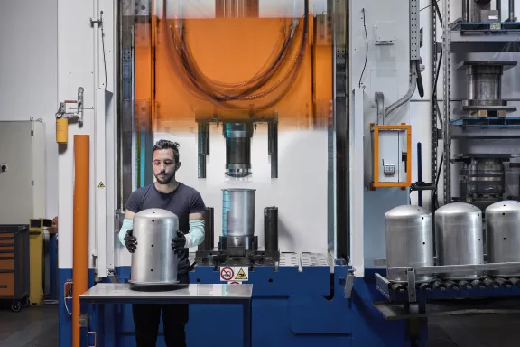
Sheet metal deep drawing is one of the most widely used cold forming processes for producing hollow, three-dimensional components from a flat metal sheet, or from a blank that has been laser cut, sheared, or punched.
Minifaber applies this process to ferrous materials, including galvanized and prepainted ones, as well as stainless steel, aluminum, copper, and special alloys, adapting every production step to the characteristics of the material and the geometry the finished component requires.
In this guide, we look in detail at how the deep drawing process unfolds, which materials are used most often, and which industrial sectors rely on it.
What is sheet metal deep drawing
Sheet metal deep drawing is the plastic deformation of a flat metal blank, which is pushed through the gap between die and punch until it takes the desired hollow shape.
Unlike machining processes, no material is removed, only deformed. The result is strong, seamless components with efficient use of the raw material.
The process requires simultaneous control of several variables: die design, the shape of the starting blank, press pressure, blank holder action, lubrication, and the mechanical behavior of the chosen material. The quality of the result therefore depends above all on careful design of every stage of the production cycle and of the tooling.
The stages of the deep drawing process
Deep drawing unfolds through sequential steps, each of which directly affects the dimensional and structural quality of the finished component.
Blank preparation
The first stage is cutting the blank, the flat piece of sheet metal from which the part takes shape. Its size and shape are calculated from the volume of material needed to reach the final geometry, taking into account the elongation the metal will undergo during deformation.
Blank size is already a process variable. A smaller blank lets the sheet flow more easily but can cause wrinkling and instability in the material. A larger blank can solve two problems: proper tensioning of the material, which gives the part greater stiffness, and wrinkling. It should be noted, however, that a larger blank can cause other wrinkles to appear, such as those at the blank edge, and can lead to severe stretching of the sheet, up to necking and fracture.
Clamping with the blank holder
In a deep drawing process, the blank is generally placed on the blank holder and clamped by the die. The blank holder is a rigid element that exerts on the blank a calibrated, adjustable counterforce against the thrust of the die. This stage is decisive for controlling material flow during the die stroke: the material moves from its outer portions toward the center and toward the gap between die and punch, taking the shape the tooling was designed to produce.
Insufficient blank holder pressure causes wrinkling, while excessive pressure causes tearing or uncontrolled thinning. In this setup, the punch is stationary and the sheet is shaped around it.
This deep drawing setup, with a fixed punch and a moving die, is the most common one. In some cases, however, it can be more useful to keep the die stationary and move the punch.
The drawing stroke
The process begins when the die, driven by the main cylinder of the press, moves down and pushes the blank holder downward. The blank, clamped between die and blank holder, rests on the top surface of the punch and, as the stroke continues, flows into the gap between die and punch to form the desired part. It is the die radius that forces the sheet into its abrupt change of direction, from flat to vertical or inclined, and it is also one of the main process adjustment parameters: a large radius makes it easier for the material to flow, while a small radius tends to hold it back.
It is not always possible, however, to make a drawn part in a single pass: everything depends on the material used and the geometry of the component. For narrow, deep parts, for example, the work must proceed in successive passes, using different dies that gradually bring the part to its final shape. This is because there is a drawing ratio limit, determined by the mechanical characteristics of the material, which cannot be exceeded in a single pass.
Work hardening complicates the process further: with each drawing pass, the material becomes progressively harder, losing plasticity, malleability, and drawability. For this reason, a heat treatment is often needed between one pass and the next to restore the material's original grain structure and, with it, its starting mechanical properties.
Trimming and complementary operations
Once formed, the component is trimmed by blanking or laser cutting to remove excess material along the edges and wherever the drawing requires it. Depending on the specifications, sizing operations may follow to correct the material's springback, along with complementary operations such as drilling, bending, or surface treatments.
Dimensional and process controls
Every batch undergoes dimensional and structural checks to verify conformity to design tolerances. Minifaber integrates these checks throughout the entire production cycle, so that any deviation is caught before the component moves on to the next operations.
Materials for sheet metal deep drawing
The choice of material affects every stage of the process described above: press parameters, die geometry, lubrication, and the number of passes all change significantly depending on whether the work involves stainless steel, aluminum, coated iron, or copper alloys.
- Stainless steel, chosen for its corrosion resistance in sectors such as medical, food equipment, and electromechanical.
- Aluminum, suited to applications where weight reduction is a key requirement, thanks to its malleability.
- Iron and coated materials, suited to high-volume industrial production where productivity and repeatability matter.
- Copper and brass, used for technical components that require electrical or thermal conductivity.
For a closer look at the characteristics of each material and how to guide the choice at the design stage, read our guide Metal Deep Drawing: how it works and when it is useful.
Industrial applications of sheet metal deep drawing
Thanks to the variety of materials that can be worked and the precision achievable during forming, sheet metal deep drawing is used in many industrial sectors.
In the medical sector, deep drawing is used to make components that require smooth, uniform surfaces that keep their stainless properties over time, which are fundamental requirements for compatibility with sterile environments. In food equipment, the same need for smooth, burr-free finishes makes deep-drawn stainless steel the preferred solution for components that come into contact with food.
In the electromechanical sector, deep drawing makes it possible to produce copper and brass components where electrical conductivity is a design requirement, as well as aluminum components where keeping weight down affects the overall performance of the system.
In professional lighting and in gas and energy distribution, deep drawing is applied to components that need mechanical strength together with a process that avoids welds and joints. In this case, the production cycle is faster and more cost-effective.
This versatility of application is why Minifaber develops deep drawing as an integrated part of its sheet metal processing offering, from die design to the finished component.
Why choose Minifaber for sheet metal deep drawing
Minifaber manages the entire deep drawing cycle in-house, from die design to the finished component, across a production area of 56,000 square meters and with a large workforce dedicated to sheet metal processing. This direct control over every stage of the process makes it possible to intervene quickly on press parameters, processing sequences, and quality controls, shortening validation times compared with supply chains that rely on outside suppliers for dies or complementary operations.
The €5.6 million technology investment in 2025 expanded the machine fleet dedicated to processing and cold forming in general, allowing Minifaber to follow orders ranging from prototypes to series production while maintaining the same dimensional quality across different production volumes. This flexibility makes Minifaber a suitable partner for both complex-geometry projects and high-volume production cycles.
Minifaber, your partner for sheet metal deep drawing
Minifaber designs and produces deep-drawn components in ferrous materials, including galvanized and prepainted ones, as well as stainless steel, aluminum, copper, brass, and special alloys, following the entire production cycle from die design to process controls.